Guide:
How to Build a Simple LED Tester
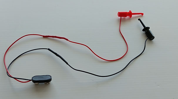
The LED tester is an optional build designed to help you quickly troubleshoot any LEDs that don’t light up in your STEM American flag soldering kit. Instead of guessing whether an LED is faulty, or installed incorrectly, this simple tool lets you confirm correct orientation and functionality in seconds. With just a 470‑ohm resistor, a 9‑volt battery, and a few basic parts, you’ll have a handy tester that will allow you to effectively troubleshoot non-functional LEDs.

LED Tester Electrical Diagram

Parts List
Parts List for LED Tester
-
1 × 470‑ohm resistor, ¼‑ or ½‑watt, any tolerance, axial leaded, through‑hole
-
2 × spring hook type, clip‑on test leads (red and black preferred)
-
1 × 9‑volt battery connector
-
1 × 9‑volt battery
-
2 × pieces of heat shrink tubing
-
Electrical tape
-
1 × LED any color to be used for verification of correct wiring of the LED tester
Component Pictures

470 Ω-Resistor
Yellow, Violet, Brown

9V Battery Connector

Test Leads

9V Battery


Electrical Tape
Heat Shrink Tubing
Equipment & Supplies
Safety Glasses
Soldering Iron, Soldering Iron Holder, Wet Sponge
Rosin Core or No-Clean Wire Solder
Diagonal Wire Cutter
Wire Stripper
Hot Air Gun
Aluminum Foil (Optional)
LED Tester Assembly Instructions
LED Tester Pre- Soldering Assembly Steps (See Picture Below)
1. Put on your safety glasses
2. About ¼ inch from the end of each resistor lead, make a 90‑degree bend on both ends of the 470 Ω resistor.
3. Pre‑wired spring‑hook test leads are sold in a variety of configurations. Cut off the termination on the end opposite the spring‑hook. Using the correct size wire‑stripping tool, strip about ¼ inch of insulation from the end of the wire, then twist the stranded wires into a tight bundle.
4. Using the correct size wire‑stripping tool strip ¼ inch of insulation from the red and black wires of the battery connector, and twist each into a tight bundle.
5. Slide the two heat‑shrink tubes onto the red and black wires of the battery connector.
6. Twist the stranded black wire of the battery connector together with the stranded black wire of the test lead.
7. Connect the red wire from the battery connector to one end of the resistor by twisting the stranded red wire around the resistor lead, starting at the 90‑degree bend.
8. Connect the red wire from the test lead to the other end of the resistor by twisting the stranded red wire around the resistor lead, starting at the 90‑degree bend.
9. Keeping the exposed black and red wires from touching each other and causing a short, connect the 9‑volt battery.
10. Attach the black test lead to the negative (short) lead of an LED, and the red test lead to the positive (long) lead.
11. If the LED lights, your wiring is correct. Proceed to solder the wires and shrink the heat‑shrink tubing over the electrical connections.
12. If the LED does not light during testing, stop and troubleshoot your tester. Do not solder the wires until the LED lights correctly when connected.

Troubleshooting Tips if Your LED Tester Is Non‑Functional
If your LED tester does not light up after assembly, check the following common issues:
-
Possible dead battery – Ensure the 9‑volt battery is fresh and providing adequate voltage.
-
Defective test LED – Try a different LED to confirm the one you’re using isn’t faulty.
-
Incorrect resistor value – Verify that the resistor is 470 Ω. Using the wrong value can prevent the LED from lighting.
-
Incorrect wiring – Double‑check that the red and black wires are connected to the correct points and that polarity is correct.
-
Bad electrical connection – Inspect all twisted or soldered joints to make sure they are secure and making proper contact.
Soldering the Tester Electrical Connections
1. Put on safety glasses.
2. Disconnect the 9‑volt battery from the electrical connector assembly. Never solder with the battery connected.
3. Protect your work surface by placing a sheet of aluminum foil under the tester assembly.
4. Arrange the twisted wires so they can be easily heated with the soldering iron tip. Avoid laying them flat against the foil.
5. Prepare the soldering iron: turn it on, allow it to reach operating temperature, clean the tip with a damp sponge, and tin the tip with a small amount of solder.
6. Apply solder to the wires: heat the twisted wires with the iron tip, then feed a small amount of solder at the junction of the iron and wires. Move the iron along the length of the twisted wires while feeding solder until they are evenly coated.
7. Finish the joint: remove the soldering iron and allow the connection to cool undisturbed.
Shrinking the Heat Shrink Tubing Over the Electrical Connections
Heat‑Shrink Tubing Insulation
-
Bend the soldered twisted wires so they lie flat. This makes it easy to slide the heat‑shrink tubing over the exposed electrical connections.
-
Bend both sides of the twisted wires attached to the resistor inward toward the resistor lead, so the twisted wire rests neatly against the resistor lead (see picture below).
-
Slide the heat‑shrink tubing over both electrical connections, covering the resistor body as well, so no electrical connections remain exposed (see picture below).
-
Bend the black twisted wire so it lies flat against the wire insulation, then slide the heat‑shrink tubing over the connection (see picture below).
-
Protect your work surface by placing aluminum foil under the wire assembly to prevent heat damage (see picture below).
-
Shrink the tubing: use a heat gun to evenly heat both pieces of tubing until they contract and form a secure electrical insulation over all connections (see picture below).