<meta name="google-site-verification" content="dC955zOHrNSQZ8zaElaYe5pdGSqnGhfNZ-p4ogURGZg" />
Circuit Board Bottom-side Assembly Instructions

Printed Circuit Board (PCB)
Secondary/Bottom-Side Assembly Instructions
-Safely First
-Follow Instructions Exactly
- Have Fun

Equipment / Supplies Required
Equipment Required
Safety Glasses
Soldering Iron / Soldering Iron Stand / Wet Sponge
Rosin or No-clean Flux Core Solder
Tweezers
Components Required
27 PCS, 510 Ohm, Surface Mount Resistors 1206 Package
1 PC, Shockley Diode - SS34 Surface Mount (D0-214) Package
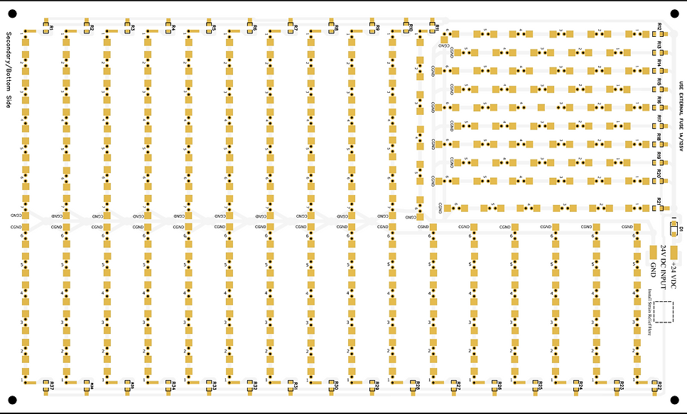
PCB Bottom-Side Unpopulated Bare Circuit Board-
Showing Surface Mount Component Locations
The component locations for resistors R1–R37 and Shockley diode D1 are printed on the bottom side of the circuit board.
Step # 1
Locate Surface Mount Resistor Soldering Pads

Step 1: Locate the Surface-Mount Resistor Pads
Identify the soldering pads designated for surface-mount resistors on the bottom-side of the PCB. These pads are labeled R1 through R37 and are illustrated in the reference diagram above.
Step # 2
Prepping the Solder Pad

Step 2: Prepping the Soldering Pad for Surface-Mount Resistor Installation
-
Tin the Soldering Iron Tip - Begin by applying a very small amount of solder to the clean, heated tip of your soldering iron. Do this by gently pressing the solder wire against the hot tip until it is lightly coated, just enough to appear slightly wet with solder.
-
Tin the Soldering Pad - Identify the narrower of the two soldering pads designated for the surface-mount resistor. Press the tip of your soldering iron gently onto this pad.
-
Apply Solder to the Pad - While maintaining gentle pressure with the iron on the pad, press the solder wire at the point where the iron tip meets the pad. After a second or two, the solder should melt and begin to coat the pad.
-
Form a Proper Solder Bump - Your goal is to create a smooth solder bump that fully covers the pad. It should not form a round ball, as this indicates improper bonding. The soldering iron must remain in contact long enough for the flux within the solder to clean the pad’s surface. Once the pad reaches soldering temperature, the solder will bond mechanically to the pad.
-
Troubleshooting If the solder does not melt and bond within 5 seconds, stop. Clean the tip of your soldering iron using a damp sponge, reapply a small amount of solder to the tip, and repeat the process. Continue until the pad is properly tinned with a smooth, shiny bump of solder.
Step # 3
Initial Placement - Tack Soldering the Resistor to the Pad

Step 3: Tack Soldering the Resistor to Its Pad
Follow the same procedure outlined in Step-2 to prepare your soldering iron tip.
-
Using a pair of tweezers, grasp the surface-mount resistor by the sides of its body.
-
Align the resistor so it is centered between the two soldering pads and lies flat against the circuit board.
-
While holding the resistor in place, heat the soldering pad that was previously tinned.
-
As the solder melts (reflows), it will bond to the metal contact on the end of the resistor.
-
Once the solder becomes molten and attaches to the resistor’s contact, remove the soldering iron.
-
Continue holding the resistor in place with the tweezers until the solder cools and solidifies — about two seconds.
-
After cooling, release the resistor. One end should now be tack-soldered to the pad.
This entire process should take only a few seconds: approximately two seconds to reflow the solder and two more seconds for it to cool and set.
Step # 4
Soldering the Opposite Side of the Tack Soldered Resistor

Step 4: Soldering the Opposite Side of the Resistor
Using a clean, tinned soldering iron with a slightly wet tip, heat both the unsoldered side of the resistor contact and its pad simultaneously. Feed solder directly into the point where the soldering iron tip, pad, and resistor contact meet.
The solder should flow smoothly, covering the entire pad and bonding the resistor contact to the pad. Once the solder has flowed evenly, remove the soldering iron and allow the joint to cool for at least 3 seconds so the solder can solidify.
If rework is needed, clean the soldering iron tip before trying again. Any excess or burned solder residue on the tip can prevent proper heat transfer and result in a poor-quality solder joint.
Step # 5
Reflowing the Solder Joint of the Tacked-Side of the Resistor - Completing the Resistor Soldering Process

Step 5: Reflowing and Final Inspection
Using a clean, slightly wet soldering iron tip, reflow the resistor’s solder joint by positioning the iron so that it makes contact with both the resistor’s metal terminal and its solder pad. Apply a small additional amount of solder to the joint as needed. Once the solder flows and covers the pad evenly, remove the soldering iron tip and allow the joint to cool.
Visually inspect both solder joints and rework if necessary, always starting with a clean soldering iron tip.
Important: If you rework one side of the resistor’s solder connection, allow at least 4–5 seconds before reworking the opposite side. Attempting to reflow both sides before the first joint has cooled and solidified may cause the resistor to shift out of alignment or become dislodged from the pads.
Shockley Diode D1 Installation Procedure


Step 3: Tack Soldering the Diode into Place
While continuing to hold Diode D1 in position—aligned between its two solder pads and flat against the circuit board—with one hand, use your other hand to hold the soldering iron.
Heat one side of the diode’s metal termination until the solder beneath it melts. Then, carefully remove the soldering iron while maintaining the diode’s position until the solder cools and solidifies, securing that side of the diode in place.
Step 4: Soldering the Opposite Side of the Tacked Diode
Allow enough time for the tacked side of the diode, solder enough time to fully cool and solifiy prior to releasing the body of the diode, with your tweezers. About 5-7 seconds, at which time you can release the body with your tweezers.
Then heat the contact opposite of the tack soldered side with your soldering iron while feeding a small amount of wire solder into where the contact and soldering pad meets.
PCB Bottom-Side Fully Assembled
